Gear Reducer Couplers With Two 1/2" Pins Between Rubber Insert
Opto-coupler is an electronic component that transfers electrical signals between 2 isolated circuits. Optocoupler also called Opto-isolator, photo coupler or optical isolator.
Oft in circuits, specially depression voltage or highly noise sensitive circuits, Optocoupler is used to isolate circuitry to forbid electrical collision chances or to exclude unwanted noises. In present commercial market, we can buy Opto-coupler with 10 kV to 20 kV input to output withstand voltage capacity, with a specification of 25 kV / uS voltage transients.
Internal Structure of Optocoupler
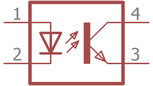
This the internal structure of the opto-coupler. On the left side pin 1 and pivot ii are exposed, information technology is a LED (Light Emitting Diode), the LED emit infrared light to the photosensitive transistor on the right side. The photo-transistor switches the output circuitry past its collector and emitter, same equally typical BJT transistors. Intensity of the LED straight controls the photograph-transistor. Since the LED can be controlled by a unlike circuitry and the photograph transistor can control different circuitry so ii independent circuits tin be controlled by Optocoupler. Also, between the photo-transistor and the Infrared LED, the space is transparent and non-conductive textile; information technology is electrically isolating 2 dissimilar circuits. The hollowed space betwixt LED and photo-transistor tin can be fabricated using Glass, air, or a transparent plastic, the electrical isolation is much higher, typically ten kV or higher.
Types of Optocouplers
In that location are many unlike types of Optocouplers are available commercially based on their needs and switching capabilities. Depending on the use there are mainly four types of optocouplers are available.
- Opto-coupler which use Photo Transistor.
- Opto-coupler which utilize Photo Darlington Transistor.
- Opto-coupler which use Photo TRIAC.
- Opto-coupler which utilize Photograph SCR.
Photograph-Transistor Optocoupler
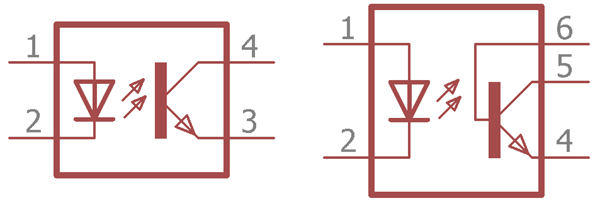
In the upper image the internal structure is shown inside a Photo-transistor Optocoupler. The Transistor type can be anything whether PNP or NPN.
Photograph-Transistor can be farther of two types depending on the output pivot availability. On the 2nd image on the left, there is additional pivot out which is internally connected with transistor'south base. This pin six is used to control the sensitivity of the photo-transistor. Frequently the pivot is used to connect with ground or negative using a high value resistor. In this configuration, faux triggering due to noise or electrical transients tin exist controlled effectively.
Also, before using Photo-transistor based optocoupler, the user must know the maximum rating of the transistor. PC816, PC817, LTV817, K847PH are few widely used photo-transistor based optocoupler. Photo – Transistor based opto-coupler is used in DC circuit related isolation.
Photograph-Darlington Transistor Optocoupler
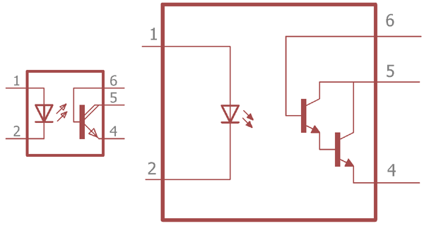
In the upper image there are ii types of symbol, internal structure of Photo-Darlington based opto-coupler is shown.
Darlington Transistor is two transistor pair, where i transistor controls other transistor base. In this configuration the Darlington Transistor provide high gain ability. As usual the LED emits infrared led and controls the base of operations of the pair transistor.
This type of opto-coupler likewise used in DC circuit related expanse for the isolation. The 6th pin which is internally connected to the base of operations of the transistor, used to control the sensitivity of the transistor as discussed previously in photo-transistor description. 4N32, 4N33, H21B1, H21B2, H21B3 are few photograph-Darlington based opto-coupler instance.
Photo-TRIAC Optocoupler
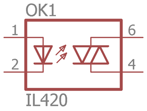
In the upper epitome the internal construction or the TRIAC based opto-coupler is shown.
TRIAC is mainly used where Ac based control or switching is needed. The led can be controlled using DC, and the TRIAC used to control AC. Opto-coupler provide excellent isolation in this instance too. Here is one Triac Application. The photo-TRIAC based opto-coupler examples areIL420 , 4N35 etc are example of TRIAC based opto-coupler.
Photograph-SCR based Optocoupler
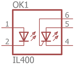
SCR correspond Silicon controlled rectifier, SCR also referred as Thyristor. In the upper paradigm a Photo-SCR based opto-coupler'south internal construction is shown. Aforementioned as like other opto-coupler the LED emit Infrared. The SCR is controlled by the intensity of the LED. Photo-SCR based Opto-coupler used in AC related circuitry. Learn more than almost Thyristor here.
Few Examples of photo-SCR based opto-couplers are:- MOC3071, IL400, MOC3072 etc.
Applications of Optocoupler
Every bit discussed earlier few Optocoupler used in DC circuit and few Optocoupler used in AC related operations. As the Optocoupler does not permit straight electric connection between ii sides, the principal application of the Optocoupler is to isolate two circuits.
From switching other application, same as like where transistor can be used to switch application the Optocoupler tin can be used. It can exist used in various microcontroller related operations where digital pulses or analog data needed from a high voltage circuitry, Optocoupler can be used for fantabulous isolation between this 2.
Opto-coupler tin be used for Air-conditioning detection, DC control related operations. Allow's see few applications of Opto-transistors.
Optocoupler for Switching DC Circuit:
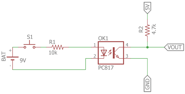
In the upper excursion a Photo-Transistor based optocoupler excursion is used. Information technology will act like a typical Transistor switch. In the schematic a depression price photograph-transistor based opto-coupler PC817 is used. The infra-blood-red led will be controlled by the S1 switch. When the switch volition be on, the 9V bombardment source volition provide current to the LED via the current limiting resistor 10k.The intensity is controlled by the R1 resistor. If we alter the value and make the resistance lower, the intensity of the led will be high making the transistor gain high.
On the other side the transistor is a photo-transistor controlled by the internal infra-red led, when the led emit infra-cherry calorie-free the photo transistor will contact and the VOUT will exist 0 turning off the load connected across it. It is needed to remember that equally per the datasheet the collector electric current of the transistor is 50mA. The R2 provide the VOUT 5v. The R2 is a pull-up resistor.
Y'all tin can see the switching of a LED using opto-coupler in the below video…
In this configuration the photo-transistor based opto-coupler can be used with the microcontroller for detecting pulses or interrupt.
Optocoupler for Detecting AC Voltage:
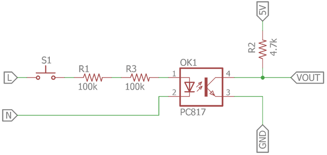
Here some other circuit is shown to discover the Ac voltage. The infra-blood-red led is controlled using two 100k resistor. The 2 100k resistor used instead of one 200k resistor is for actress condom for short-circuit related condition. The LED is continued across wall outlet Line (L) & Neutral line (N). When the S1 is pressed the led showtime to emit infra-red light. The photograph transistor makes a response and converts the VOUT from 5V to 0V.
In this configuration the opto-coupler tin can be connected across low voltage excursion such equally microcontroller unit of measurement where the AC voltage detection is required. The output volition produce square High to Low pulse.
As of at present the beginning circuit is used to control or switching the DC circuit and 2d is to detect the AC excursion and control or switch DC circuit. Adjacent we will see controlling AC excursion using DC circuit.
Optocoupler for Decision-making Air-conditioning Circuit using DC voltage:
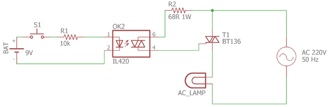
In the upper circuit The LED is again controlled past 9V battery through 10k resistor and the land of the switch. On the other side a photo-TRIAC based opto-coupler is used, which control the AC LAMP from the 220V AC outlet. The 68R resistor is used to Control the BT136 TRIAC which is controlled by the photo-TRIAC within the opto-coupler unit.
This type of configuration is used to control electric appliances using low voltage circuitry. The IL420 is used in the upper schematic which is a photo-TRIAC based Opto-coupler.
Other than this type of circuitry an opto-coupler can exist used in SMPS to sending secondary side brusk-excursion or over electric current status information to the chief side.
If y'all want to meet Optocoupler IC in existent action, check below circuits:
- Introduction to Octocoupler and Interfacing with ATmega8
- Prepaid Free energy Meter using GSM and Arduino
- IR Remote Controlled TRIAC Dimmer Excursion
- Raspberry Pi Emergency Light with Darkness and AC Power Line Off Detector
- IR Remote Controlled Home Automation using PIC Microcontroller
DOWNLOAD HERE
Gear Reducer Couplers With Two 1/2" Pins Between Rubber Insert UPDATED
Posted by: marionwhanterrene.blogspot.com
Gear Reducer Couplers With Two 1/2" Pins Between Rubber Insert UPDATED. There are any Gear Reducer Couplers With Two 1/2" Pins Between Rubber Insert UPDATED in here.

